Forces on Bolts on Side Plate Shear Connection
Structures are generally designed in large pieces like a building frame, however they are constructed in small segments linked together by connection elements. As the saying goes, a chain is only as strong as its weakest link. You can have the strongest beam on the planet, but if the connection capacity is not congruent with the beam capacity, you’re essentially just wasting material on the beam. And to design a connection you first must understand the load path within the elements connecting the members. Today we’re going through the forces acting on bolts on a side plate shear connection.
STEEL
10/15/20233 min read
Structures are generally designed in large pieces like a building frame, however they are constructed in small segments linked together by connection elements.
As the saying goes, a chain is only as strong as its weakest link. You can have the strongest beam on the planet, but if the connection capacity is not congruent with the beam capacity, you’re essentially just wasting material on the beam. And to design a connection you first must understand the load path within the elements connecting the members.
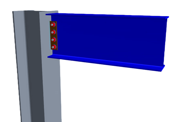
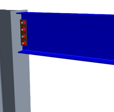
Today we’re going through the forces acting on bolts on a side plate shear connection.

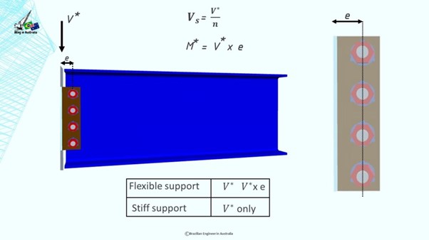
You have two ways of treating this connection. You can either imagine the side plate as an extension of the web of the beam or you can imagine that the plate welded to the column cantilevers from the support and the bolts become a hinge point. The first option is the behavior for the case where the connection is made to a flexible support. While the second option is the behavior for the case of a stiff support.
For a stiff support we design the bolts for the V* shear force only. However, for a flexible support, we should design the bolts for V* and also for V* times the eccentricity between the centroid of the bolt group and the support, which is our design bending moment M*.
The Australian Institute of Steel Construction states that no support is purely flexible nor purely stiff, but rather lies somewhere between the two extremes. It also mentions that it is not possible to quantify the behavior for each individual connection. Therefore, we are going to always use the flexible support design model and account for the bending moment. It’s safer and it will take only an extra 30 seconds to do it.
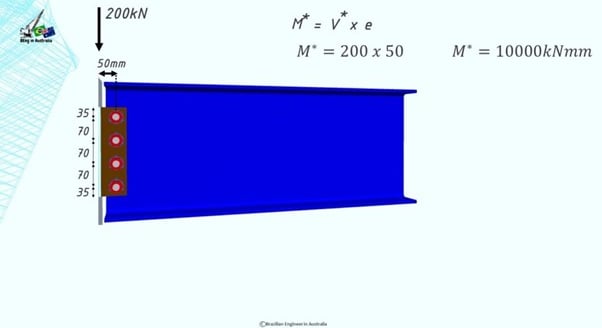
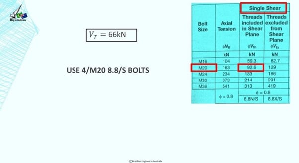
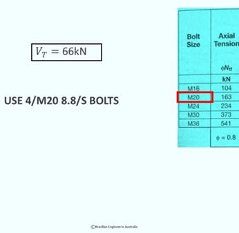
We are going to design a side plate with a single line of 4 bolts.
The vertical shear force in each bolt is pretty straightforward. It’s just the V* divided by the number of bolts.
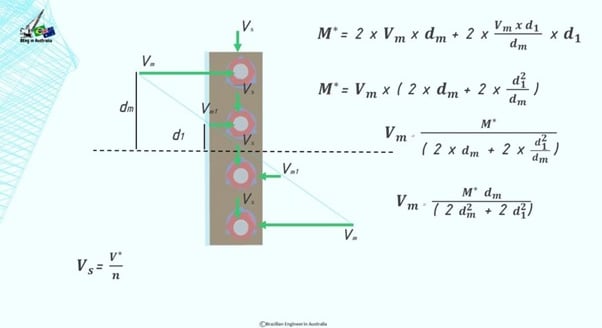
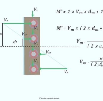
The design bending moment is V* times the eccentricity, which acts in the centroid of the bolt group and it will result in horizontal shear forces on each bolt.
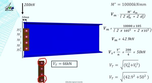
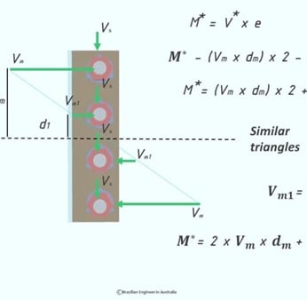
The magnitude of each one of these horizontal shear forces will be different depending on the distance from the centroid. What that means is that the further away from the centroid, the higher the force.
Vm is the shear on the very top bolt and also in the very bottom bolt because their distance to the centroid is the same.
And there is Vm1 which is a smaller shear force acting on the other two bolts.
As an engineer we’re going to design the worst case scenario, because we’re not going to specify different bolt sizes in this connection.
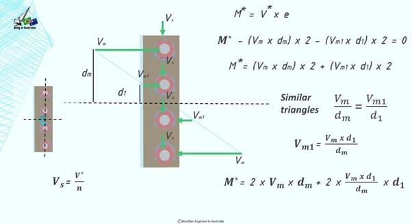
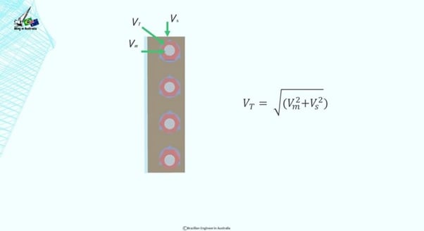
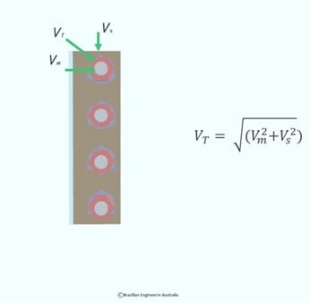
This is the free body diagram and as you are aware, structural engineers like systems is equilibrium. We love motionless structures. And if the sum of the forces or moments to a point is not equal to zero, your structure is probably walking or moving and that’s not good.
And we know that the magnitude of a vector can be calculated by taking the square root of the sum of the squares of its components.
Let's do a numerical example so you can cement this concept in your head:
Imagine we have a simply supported beam and by drawing the shear force diagram, we get that threre is a shear force of 200kN acting on the connection.